


Words and Photos: David Biggs
This issue’s questions come from a Mason Contractor, an Architect, and an Engineer. What questions do you have? Send them to info@masonrymagazine.com, attention Technical Talk.
Q. A Mason Contractor writes that on a recent cavity wall project, an inspector cited his crew for not having full head and bed joints in the brick veneer. An area of the veneer was subsequently removed to assess the workmanship. There were some instances of furrowing in the bed joints and clipped joints (incomplete mortar) on the brick head joints. The mason asks what degree of mortar imperfections is acceptable.
A. The importance of full head and bed joints cannot be understated. Nearly every project specification states that the joints should be full. There have been various lawsuits resulting from imperfections.
The mortar is the first line of defense to prevent water intrusion into the cavity and also limiting the possibility of efflorescence. Head joints are particularly vulnerable to water penetration due to the reduced compression in the joints. Any unfilled head joints make the vulnerability worse.
The masonry standard, TMS 602, Specification for Masonry Structures, requires full head and bed joints. It is one of the only aspects of masonry construction where no tolerances are provided. TMS 602 is the defining standard because it is referenced in the International Building Code and most local building codes.
Article 3.3B.5 states:
5. Solid units – Unless otherwise required, place mortar so that bed and head joints are fully mortared and:
1. Do not fill head joints by slushing with mortar.
2. Construct head joints by shoving mortar tight against the adjoining unit.
3. Do not deeply furrow bed joints.
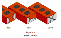
The Brick Industry Association provides some guidance relative to head joint construction. Technical Note 7B, Water Penetration Resistance – Construction and Workmanship, includes the following figure (courtesy of BIA) to distinguish unacceptable head joints. The first shows the clipped joint and the second is another incomplete joint.
The only relief for incomplete mortar joints comes from TMS 602, Article 3.3b.5 Commentary which states:
5. Solid units- Normal construction practices can create mortar joints with minor imperfections and small voids that have no significant effect on the masonry assembly. Mortar joints on the face of masonry need to be filled to provide the specified mortar joint finish.
While the commentary states that minor imperfections are likely, it does not have legal merit because it is purely advisory. Thus, it falls to the interpretation of the inspector as to what constitutes a minor imperfection.
Summary:
1. Fully mortared head and joint joints are essential workmanship characteristics that must be maintained.
2. The building code does not provide any tolerance for unfilled mortar joints.
Q. An Architect has seen photographs in articles of sloping masonry veneer walls and asks about their structural design. How are these designed using the masonry standards? They to exceed the corbelling requirements that engineers give us.
A. Thank you for the question. Sloping veneer walls are an extreme example of corbelling as seen in the following buildings. The first two have brick veneer and the third is a sandstone veneer.

(courtesy Business Insider Australia)

(architect MSME Architects, Atlanta, GA)
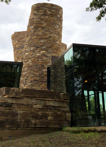
(architect MSME Architects, Atlanta, GA)
In the United States, TMS 402-22, Building Requirements for Masonry Structures provides requirements for corbelling a veneer. There are prescriptive limits on the incremental stepping of each unit and the total stepping as shown in the next figure.
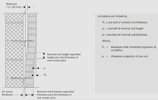
(courtesy of The Masonry Society)
Following these criteria, you quickly realize that sloping walls cannot be designed using prescriptive methods; the limits only allow small corbelling. Fortunately, TMS 402 allows veneers to be designed using either the Prescriptive Method or the Engineered Design Method of Chapter 13. (In previous editions, the engineered method was termed alternative design.) With the flexibility inherent in the Engineered Design method, the designer then can engineer a solution for sloping walls.
The structural wall (backup) is usually sloped to match the veneer by using structural steel or cold-formed metal framing. For the veneer itself, one major challenge is the anchorage of the veneer to the framing. For sloping walls, the anchor loads can be either in constant tension or compression under gravity loads dependent on the slope of the wall outward or inward, respectively. The TMS 402 prescriptive anchorage requirements are unlikely to be adequate especially because they rely on anchors bedded in mortar. A mechanical anchorage system is preferred.
The following figure is taken from published information on the Australian project Special brick units were fabricated with a groove that accepts both a reinforcement wire and a stainless steel adjustable anchor and tie. The anchor is face-attached to the framing.
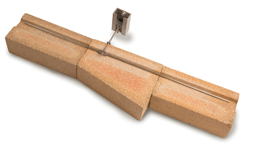
(Credits: Masonry Madness, STRUCTURE magazine, May 2020. Written by Cathy Inglis of Brickworks and Jonathon Turley, SE of Aurecon.)
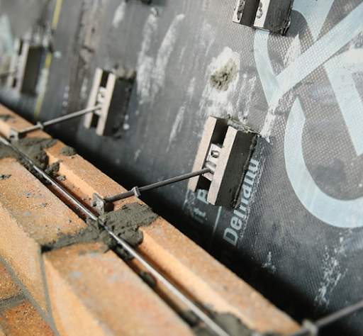
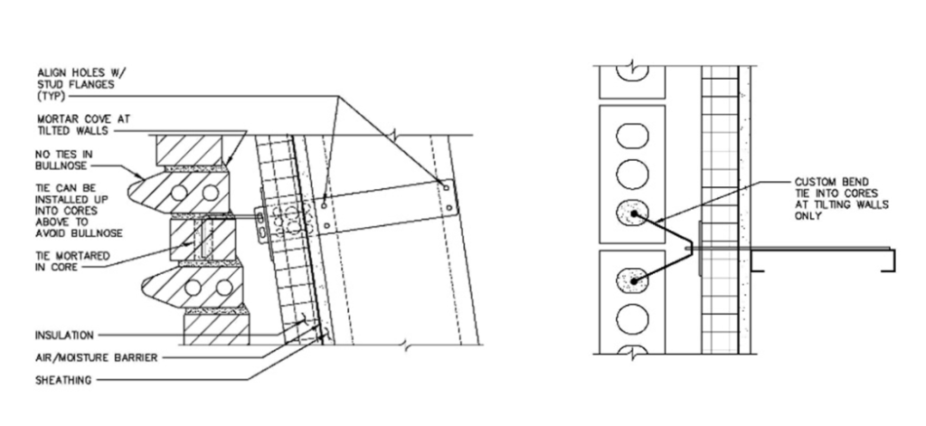
The next figure was developed by this author for the US brick project. The stretcher units were standard cored units; the architect mixed in bullnose units for architectural effect. The stainless steel anchor and tie system is a standard product manufactured by FERO Corporation; the standard V-ties were modified so the legs are vertical rather than horizontal to anchor into the cores. The anchors are side mounted to the cold-formed metal framing to place the fasteners in shear, not tension. This system has also been used for the sandstone veneer project shown previously; holes were drilled in the bed joints of the stone for the legs of the ties.
Summary:
1. Sloping masonry veneer is possible using the Engineered Design method of TMS 402.
2. The veneer anchorage is a primary design element for sloping walls. The recommendations are that the anchorage and tie system be stainless steel and that they provide a mechanical anchorage to the veneer.
3. There are many other considerations for proper barriers, flashing, weeps, etc. that must be included as with any masonry veneer wall.
Q. An Engineer asks about testing to determine the load capacity of retrofit anchors. She states that some manufacturers provide tables for their products and others only provide installation guides. She’d like to know the actual in-situ capacities of the anchors she selects.
(Note: This question was first presented in the last article. However, we addressed only the capacity of through bolts in CMU. This article will discuss post-installed retrofit anchors.)
A. Most manufacturers provide design tables or software that gives load tables for post-applied anchors embedded in masonry. These anchors might be either chemical anchors or mechanical anchors. They typically are developed for new construction.
The manufacturers generally have anchor capacities developed for concrete with some variables being f’c, cracked versus uncracked conditions, temperature, and moisture. The concrete industry has invested in more research than the masonry industry and therefore ACI 318 is more complete as to how to analyze and design anchors for concrete.
TMS 402, Building Code Requirements for Masonry Structures, is intended only for new construction and does not address retrofit (post-installed) anchors. Section 9.1.6 Commentary only leads you to the manufacturers’ literature.
Commentary 9.1.6 Anchor bolts embedded in grout
Design of anchor bolts embedded in grout may be based on physical testing or, for headed and bent-bar anchor bolts, by calculation. Due to the wide variation in configurations of post-installed anchors, designers are referred to product literature published by manufacturers for these anchors.
This is further limiting in that it only mentions anchors set in grouted units.
The reality is there is a need for retrofit anchors in masonry whether it is existing or new, grouted or hollow. So, testing verification is a wise decision. The standard for such testing is ASTM E3121, Standard Test Methods for Field Testing of Anchors in Concrete or Masonry. As mentioned, concrete has more complete information such as ASTM E488, Standard Test Methods for Strength of Anchors in Concrete Elements.
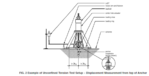
The following figure shows a proposed test setup by ASTM E3121 using a displacement gauge.
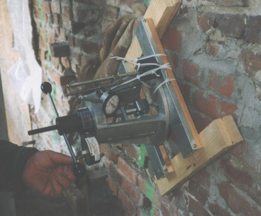
The following figure is an actual test setup on an existing masonry wall. It can be used with any masonry. The embedded anchor rod in the masonry to be tested is attached to the through-jack (there are many variations available commercially) using a coupler to an extended piece of rod. The jack then pulls the embedded rod while the operator reads the force. The equipment has been supplemented with a deflection gauge to determine the pullout movement or elongation of the anchor.
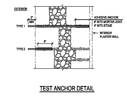
The following figure shows a schematic of a test of a historic stone wall with rubble fill. Two tests were performed to assess the ability to anchor the inner and outer wythes together when installed from the exterior. In Test 1 for the inner wythe, the anchor was debonded except at the inner wythe; For Test 2, only the outer wythe was tested. The lower value controlled the potential anchor capacity of a through wall anchor attached to both wythes.
The next figure shows a graph of one of the results. The load was applied incrementally; the ASTM procedure was modified such that subsequent increments were not applied until the anchor movement was stopped to identify any slip or creep movement.
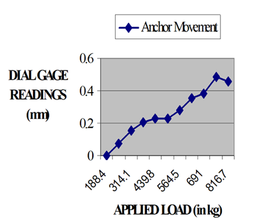
The working capacity is determined by the maximum load or the load at which creep begins divided by a safety factor (usually 4 or 5).
Summary:
1. Manufacturers’ data on retrofit (post-applied) anchors mainly pertain to new grouted construction; some have data for hollow units.
2. Field verification testing procedures are available through ASTM E3121.
Thank you again for following this column. Remember, by bonding, we get stronger! Keep the questions coming. Send them and your comments to info@masonrymagazine.com, with attention to Technical Talk. If you’ve missed any of the previous articles, you can find them online for Technical Talk, Bonding with Masonry at Masonry Design (https://www.masonrydesignmagazine.com/?s=biggs).
David is a PE and SE with Biggs Consulting Engineering, Saratoga Springs, NY, USA (www.biggsconsulting.net), and an Honorary Associate Professor with the University of Auckland, NZ. He specializes in masonry design, historic preservation, forensic evaluations, and masonry product development.
Keywords for this issue: mortared joints, sloping veneer, corbels, anchorage, testing, retrofit anchors, post-installed anchors, ASTM E3121