


Words and Figures: David Biggs
This month’s questions come from engineers and a mason contractor. What questions do you have? Send them to info@masonrymagazine.com, attention Technical Talk.
Q. A Mason Contractor writes that they are strengthening a building and the project specifications require the use of self-consolidating grout to grout the new reinforcement. They haven’t used self-consolidating grout before and want to know why this would be required instead of conventional masonry grout.
A. Thank you for the question. Self-consolidating grout has been available for many years, but it still is not commonly used in some regions.
Masons usually use conventional fine or coarse masonry grout for new construction. Specifications reference ASTM C476, Standard Specification for Grout for Masonry. Conventional masonry grout is composed of Portland-cent, lime, aggregate, and possibly a retarding admixture.
Self-consolidating grout is permitted for use in TMS 402, Building Code Requirements for Masonry Structures, and TMS 602, Specifications for Masonry Structures. The definition of self-consolidating grout is “A highly fluid and stable grout typically with admixtures, that remains homogeneous when placed and does not require puddling or vibration for consolidation.” The last portion of the definition is significant; puddling or vibration is not required!
Self-consolidating grout is commonly more expensive than conventional grout, but the installation cost is usually less because it does not require consolidating and reconsolidating.
Conventional grout requires a slump between 8 and 11 inches and puddling or vibration is required to consolidate and reconsolidate the grout in lifts. Self-consolidating grout is so fluid that it is not measured by slump height but rather by slump flow (Figure 1). Fluidity is the key to its use for strengthening existing walls.
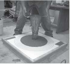
Figure 2 shows a CMU wall that was found to be missing reinforcement and supplemental steel was to be added. The wall cuts are for the insertion of the new bars and their lap slices.
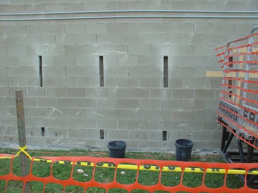
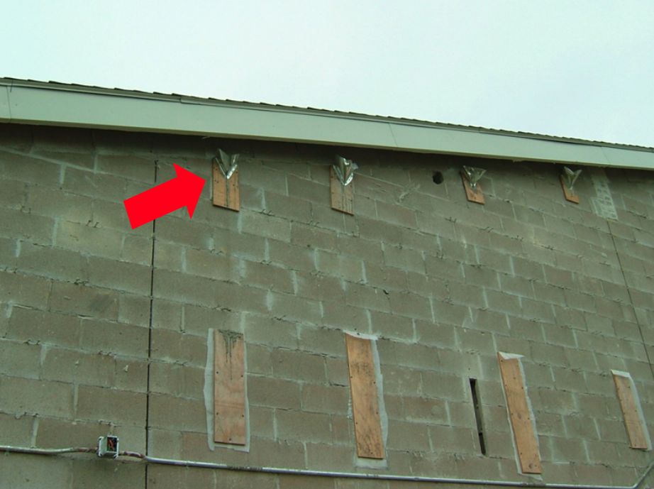
Figure 3 shows the grout openings formed and filled after the vertical reinforcement was installed. The red arrow points to an access port at the top of the pour for the placement of the self-consolidating grout. Self-consolidating grout is ideal for this application because it requires no consolidation. Installing a vibrator into the wall would be a challenge.
The self-consolidating grout is pre-blended and can be delivered in bags and mixed on site, but many masons prefer the grout pre-mixed and delivered by a ready-mixed truck similar to concrete. The mix is proportioned to achieve a desired compressive strength and Visual Stability Index.
Some limitations are that:
– admixtures cannot be added on site,
– the minimum strength is 2,000 psi or f’m, whichever is greater,
– the maximum strength should not greatly exceed 5,000 psi per TMS 402, Strength provisions,
– the grout manufacturer’s recommendations should be followed regarding adding water or admixtures on site.
Summary
1. Mason contractors should consider self-consolidating grout for applications where consolidating and reconsolidating conventional grout would be difficult.
2. Self-consolidating grout is measured by flow, not slump.
Q. An Engineer asks about testing to determine the load capacity of retrofit anchors. She states that some manufacturers provide tables for their products and others only provide installation guides. She’d like to know the actual in-situ capacities of the anchors she selects.
A. This is a very interesting and astute question. TMS 402 does not address through bolts.
Because there were no reported tests on masonry through bolts, a National Science Foundation (NSF) research project on Hybrid Masonry (NEESR-CR: Hybrid Masonry Seismic Structural Systems) included testing for through bolts. This work was highlighted in a series of two articles by Gaur Johnson and Ian Robertson of the University of Hawaii (Hybrid Masonry Connections and Through-Bolts, https://www.structuremag.org/?p=9919 and https://www.structuremag.org/?p=10144).
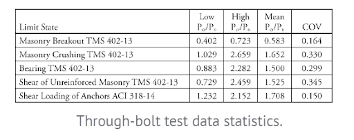
Figure 4 is taken from those articles and shows the failure modes considered in the research. The walls were considered unreinforced. Four of the modes were then compared to TMS 402 criteria while the fifth was compared to ACI 318.
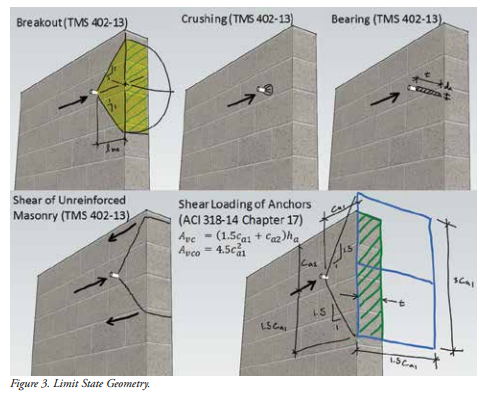
Figure 5 summarizes the results of the testing. Pcr is the first cracking value while Pu is the calculated nominal strength using either TMS or ACI standards listed in the table. A Pcr/Pu ratio of less than 1.0 indicates the calculated value is unconservative.
Summary:
1. The testing was done without reinforcement. Since most engineers will use reinforcement in the masonry walls, the test values for the through bolts are conservative relative to breakout and edge shear.
2. The testing was performed on a small sample of specimens and should not be taken as conclusive. However, if engineers are using TMS and ACI formulas, this work gives some data on through-bolt expected performance.
Q. An Engineer writes that he has to design a fix for a cracked unreinforced masonry (URM) brick wall from the 1920s that is three wythes thick (Figure 6 is a similar building to the one you described). The crack occurred in a shear wall during an earthquake. A Mason Contractor has suggested using one of the commercially-available systems to install helical bars in the bed joints. The Engineer wants to know if this is a proven method for repairing cracks.

A. Thank you for this question. It opens an interesting discussion on crack repair techniques.
Yes, the contractor has proposed a proven system for crack repair. But the question remains whether it is the right system for your project since it is a shear wall. Figure 6 shows diagonal shear cracks in the exterior wall. For your specific application, you need to both stabilize the crack and to strengthen the wall to seismically restore its lateral load carrying capacity.
The method proposed by the contractor is known as near-surface mounted reinforcement (NSM) installed horizontally. It is commonly used for repairing concrete and masonry construction. When used with brick masonry, the bed joints are raked out to a depth of about 1-1/2 inches; the underlying mortar must be sound. Then a layer of mortar is installed into the joint in lifts for a total of about 1/2 inches. (Some systems recommend a bonding agent be applied before the mortar.) Before the mortar cures, either a helical bar or threaded rod is inserted into the joint as reinforcement and pressed into the mortar. Finally, the remainder of the mortar is installed and tooled. The reinforcement then provides tensile strength across the joint.
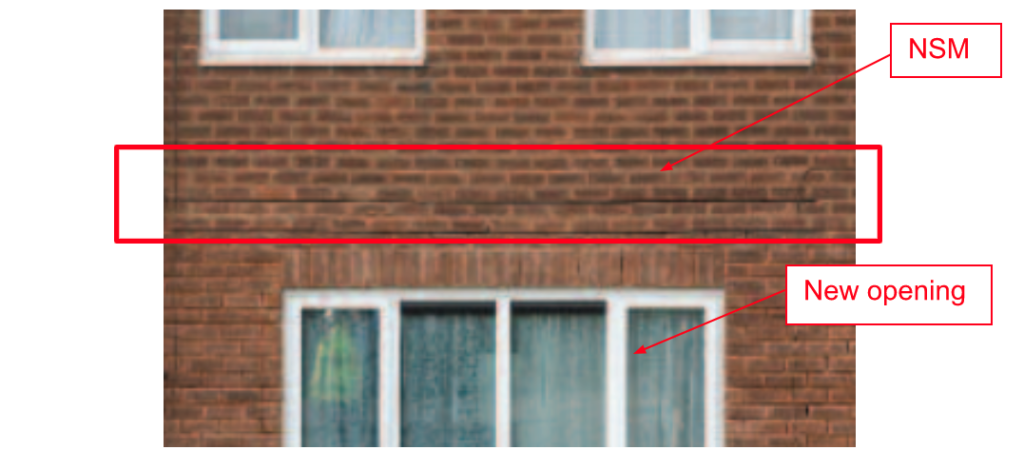
Next, we need to consider when the NSM method is applicable. One common use of NSM is to provide flexural strength over a new opening in a masonry wall (Figure 7). In this case, the NSM was installed in the wall above so the wall could be transformed into a reinforced beam to carry gravity loads and out-of-plane lateral loads. Once the NSM was cured, the new opening below was created, and the large window was installed with its lintel to support the soldier brick beneath the NSM.
A second common use of NSM is to stabilize masonry cracks. Crack stabilization is distinct from structural repair and strengthening. The goal of the stabilization is to keep the crack from reopening under thermal effects and prevent water penetration.
Cracks occur for various reasons. Excluding structural distress due to dynamic effects such as earthquakes, floods, and wind, the reasons primarily are masonry movements due to drying shrinkage, moisture expansion, corrosion-induced expansion, and thermal effects. To stabilize a crack, it is necessary to a) eliminate the source of the movement and b) stitch the crack together to minimize its chance of reopening due to thermal effects (you can’t stop thermal changes).
Figure 8 shows a brick wall that cracked because the concrete foundation had a shrinkage crack that extended into the masonry above. This was not structural. After the shrinkage was complete, both the foundation crack and the masonry crack were stabilized by NSM on the exterior only. The cracks were cleaned of all damaged mortar and then repointed. If desired for aesthetics, cracked brick can be replaced.
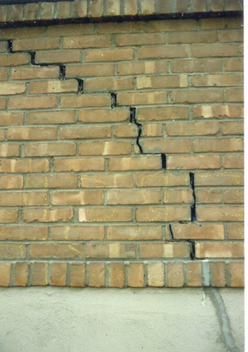
Figure 9 shows another building with a diagonal crack requiring stabilization; the bed joints to receive NSM (joint reinforcement of helical bars) are visible.
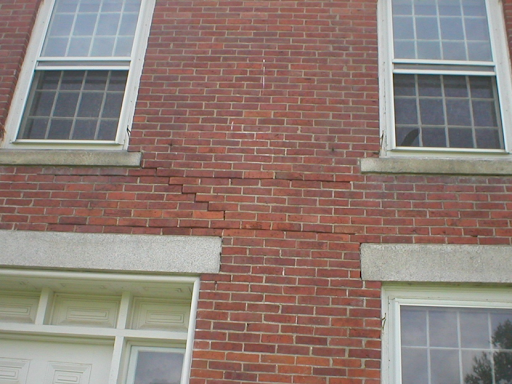
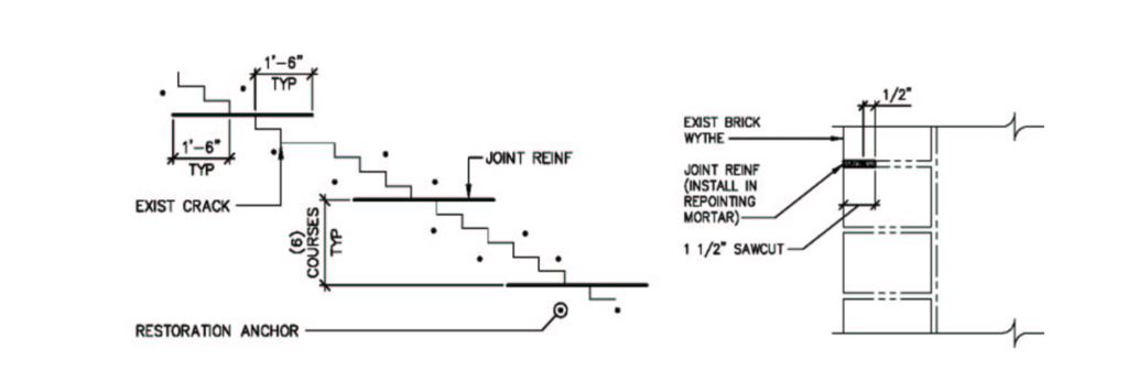
Figure 10 shows a typical stabilization detail. The extended length on either side of the crack is dependent upon the slope of the crack; preferably the extension is greater than the development length of the bar selected. The detail also shows restoration anchors on either side of the crack which are mechanical or chemical anchors in the mortar joints, much like veneer anchors. They are part of the stabilization since the brick is usually not well supported adjacent to the crack. The crack is generally repointed but not full depth.
Finally, we come to your project with the shear wall. In addition to stabilizing the crack, the wall must be strengthened to provide the required structural capacity. Horizontal NSM will stabilize the crack, but the question is whether NSM can also be used for strengthening.
Research from New Zealand and Australia (Ismail, Petersen, Masia, Ingham, Diagonal shear behaviour of unreinforced masonry wallettes strengthened using twisted steel bars, Construction and Building Materials, Volume 25, Issue 12, pp. 4386-4393, December 2011) tested two leaf (wythe), URM brick wallettes for diagonal shear. The research compared the URM samples before and after adding NSM that was either horizontal only, vertical only, or a grid. The reinforced samples had the reinforcement added on one or both faces of the walls. The results indicated NSM could be useful but to varying degrees.
For your project, adding horizontal NSM to the exterior of the wall will improve the shear capacity and pseudo ductility of the wall. However, you’ll need to:
– repoint and fully inject the crack to establish its original uncracked strength. Injection is not commonly done just for stabilization but is essential for strengthening;
– install the NSM the full width of the shear elements, not just at the cracks;
– determine if the added capacity from the reinforcement meets your design requirements. The research provides data on the other options if additional reinforcement is needed.
Summary:
1. Horizontal NSM can be used for flexural strength improvement, crack stabilization, and shear strengthening.
2. Crack stabilization with NSM requires the source of the movement that caused the crack to be eliminated.
3. NSM can be used on one of both faces of a cracked wall to strengthen a wall. Research should be consulted to guide engineers until NSM becomes available in masonry codes such as ACI 440.
4. Strengthening a cracked wall with horizontal NSM requires restoring the wall to its uncracked strength by repointing and grout injection.
Thank you again for following this column. Remember, by bonding, we get stronger! Keep the questions coming. Send them and your comments to info@masonrymagazine.com, attention Technical Talk. If you’ve missed any of the previous articles, you can find them online for Bonding with Masonry at Masonry Design (https://www.masonrydesignmagazine.com/?cat=bonding-with-masonry).
David is a PE and SE with Biggs Consulting Engineering, Saratoga Springs, NY, USA (www.biggsconsulting.net), and an Honorary Associate Professor with the University of Auckland, NZ. He specializes in masonry design, historic preservation, forensic evaluations, and masonry product development.
Keywords for this issue: self-consolidating grout, lateral support, through-bolts, post-tensioning, strengthening, crack repair, NSM