Words: David Biggs
This month’s questions come from an architect, a mason contractor, and an engineer. What questions do you have? Send them to info@masonrymagazine.com, attention Technical Talk.
Q. An Architect writes that they are considering using either clay brick veneer or architectural CMU veneer for an upcoming project. They commonly use clay brick veneer without any horizontal joint reinforcement. But, they have been advised to use horizontal joint reinforcement if they use architectural CMU. Is this necessary to use joint reinforcement with architectural CMU?
A. Thank you for the question!
The two primary reasons for using horizontal joint reinforcement in any veneer are either a) crack control due to shrinkage or b) structural reinforcement. While all materials undergo thermal shrinkage, horizontal reinforcement is generally required due to control material shrinkage rather than just thermal effects. We’ll discuss this.
Clay Brick Veneer
1. Clay brick is manufactured in a kiln where temperatures reach approximately 2000°F. The result is the moisture is baked out of the clay and the resulting brick unit is the smallest it will be in its life. Upon cooling and exposure to normal humidity or atmospheric conditions (rain or snow), the brick begins to absorb moisture and undergo expansion growth. This expansion continues even after the veneer is constructed with mortar. To control the expansion, the Brick Industry Association’s recommendations are to install movement joints that are commonly referred to as “expansion” joints.
Because the clay undergoes material expansion, not shrinkage, horizontal joint reinforcement is not needed for crack control.
2. Structurally, there are conditions when joint reinforcement is required in clay brick veneer. The first condition is when the veneer is laid in “other than running bond”. Whether the veneer is clay or CMU, TMS 402, Building Code Requirements for Masonry Structures requires that a minimum of one W1.7 wire (9 gauge) is used in the veneer at a maximum spacing of 18 inches.
The second condition is for seismic anchorage. In the 1995 TMS 402, a seismic anchorage of horizontal joint reinforcement mechanically attached to the veneer anchors was introduced (see Figure 1). It applied to veneers in Seismic Design Categories (SDC) E and F only. Based upon subsequent research, including full-scale building shake-table tests, the seismic anchorage requirement was removed from TMS 402 in 2013. That research indicated that horizontal joint reinforcement in the veneer was not necessary for seismic loads.
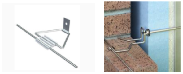
While TMS 402 discontinued the need for horizontal joint reinforcement attached for seismic anchorage, the requirement remains in some local state and city codes. So, it’s best to check with your local codes.
Architectural CMU Veneer
Concrete masonry is a molded product made from low-slump concrete and is usually cured at high humidity in a moisture chamber. During curing, the units absorb the moisture and expand and the resulting unit is the largest it will be in its life. If protected against water penetration, the CMU will dry out and its moisture will stabilize near the prevailing humidity level of its surroundings. The subsequent drying will result in shrinkage of the material and the veneer wall.
To control cracking due to shrinkage, the National Concrete Masonry Association’s recommendations (NCMA TEK 10-04, Crack Control for Concrete Brick and Other Concrete Masonry Veneers) are to install movement joints that are also referred to as “control” joints at a maximum spacing of 20 feet. Furthermore, they recommend placing horizontal joint reinforcement in the veneer (see Figure 2). If joint reinforcement is not used, cracking can be expected at 8- to 10-foot intervals.
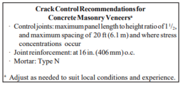
As mentioned with Clay veneer, check your local state and city codes to determine if horizontal joint reinforcement mechanically attached to the veneer ties is required for seismic anchorage
Summary:
– Clay brick veneer and CMU veneer both require horizontal joint reinforcement when laid in other than running bond.
– Architectural CMU always requires horizontal joint reinforcement to control shrinkage cracking unless a very close spacing of the movements is used (approximately 8- to 10-feet).
– Architects and engineers should refer to local codes to determine if seismic reinforcement is required in any veneer.
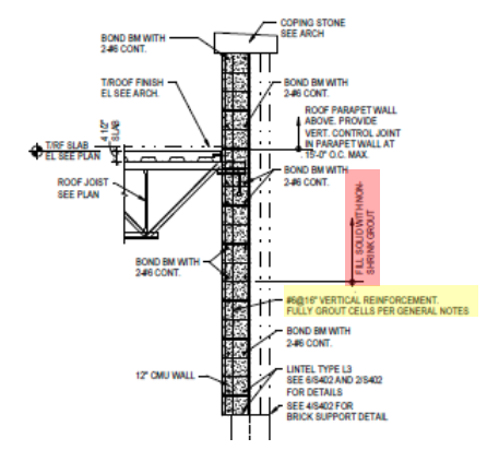
Q. A Mason Contractor sent in the attached detail (Figure 3) from a project they are bidding. In the red highlighted box, the note requires the CMU in a specific area to be filled solid with non-shrink grout. The mason questions whether non-shrink grout is necessary or desirable. They have not seen this before on a design.
A. This is an interesting issue. In the detail that was provided, another note states to “fully grout” cells with reinforcement (yellow highlighted box). It does not mention non-shrink grout. In addition, the project’s masonry notes and specifications refer to masonry grout meeting ASTM C476, Standard Specification for Grout for Masonry.
Non-shrink grout is a hydraulic cement grout per ASTM C1107, Standard Specification for Packaged Dry Hydraulic-Cement Grout (Nonshrink). It usually comes pre-packaged, only water is added, sets rapidly, and achieves high strength. ASTM lists the uses as under applied load (such as to support a structure, a machine, and the like) where a change in height below initial placement height is to be avoided. It never lists being used to infill masonry.
The material is designated non-shrink since there are ingredients that are shrinkage compensating. Per ASTM C1107, the non-shrink grout initially expands by up to 4% +/- before it starts to shrink. The subsequent shrinkage of the material results in a net expansion of between 0% and 0.3%.
Using non-shrink grout to fill CMU is a recipe for the disaster! The non-shrink grout’s initial expansion will blow the CMU apart much like what is seen when water freezes in a CMU cell.
To avoid possible cracking of the masonry, we also recommend not using non-shrink to set bearing plates on masonry. Any unexpected confinement of the non-shrink grout can exert high stress on the masonry even if its not used as infill.
Our overall recommendation is to issue an RFI to the design team and request a change from non-shrink grout to masonry grout and state the concern over expansion splitting caused by the non-shrink grout.
Summary:
– Non-shrink grout should never be used to infill CMU or any masonry. Masonry grout was developed specifically for filling CMU and reinforced brick.
– Using non-shrink grout under bearing plates set on masonry could cause cracking as well.
Q. An Engineer is asking for advice for the design and detailing of 16”-wide brick beams. The Project Architect wants the exposed masonry beam “look” for interior structural beams similar to what is seen in Figure 4. The Architect wants to avoid the detailing problems with steel lintels, soaps, hung brick, and exposed structural steel. The Engineer has been using BIA Technical Notes 17B – Reinforced Brick Masonry – Beams and 17M – Reinforced Brick Masonry Girders – Examples to design the beams.
The Engineer asks:
– From a design perspective, can the beam be designed with a concrete core and faced with brick?
– For the detailing, how is the bottom brick anchored to the beam? If the beam cracks, will the bottom brick break away?
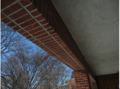
Thanks for the question. Brick beams are a great structural solution but there is a lack of good published details.
To answer your first question, the “core” as you mention would not be constructed of concrete; masonry grout is intended for use with masonry beams. As seen in the technical notes you mentioned, the brick facing retains the grout and works compositely with the grout.
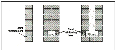
Regarding the detailing question, Architect Christine Beale has published some excellent articles and books. Her 1993 article, Lintel design and detailing (Concrete Construction Article PDF_ Lintel Design and Detailing (1).pdf) is still a valuable resource. She included a cross-section of possible brick lintels (see Figure 5).
There are several points to be made from these details.
– The first detail has no grouted core. The second and third details include the brick and a grouted core acting together compositely.
– There is no physical attachment of the bottom brick in any of these details. The beams rely on mortar and grout bond to retain the brick.
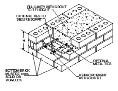
The Brick Industry Association (BIA) Technical Note 17B has a detail for 16”-wide brick beams (see Figure 6). The bottom bricks are solid and laid flat. The detail shows “optional” vertical ties into the grouted core from the head joints of the bottom bricks; there are no ties from the face bricks. The vertical ties in the head joints rely on the mortar bond.
When faced with the same questions asked by the Engineer, I chose to a) use the full composite width of the masonry beam and b) install mechanical anchors to retain the soffit (bottom) brick. Figure 7 shows a detail that has been used successfully on previous projects for 16”-wide beams. Readers can find more information from a case study at https://www.structuremag.org/?p=8511.
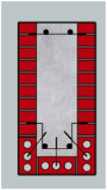
The beam was designed with sufficient depth to not require shear stirrups; the upper cross wire and lower stirrups provide for bar alignment. Using cored bricks, the bottom bricks are anchored to the grouted core with “Z”-shaped anchors. The face bricks at the bottom are used as rowlocks. The designer can also use joint reinforcement or cross wire to connect the exterior brick to resist grouting pressures.
Figure 8 shows another possible option for mechanically anchoring the bottom bricks if solid bricks are used without rowlocks. It has some similarities to Figure 7. This detail requires much more time and effort to execute. I have not used this exact detail so make your own decision.
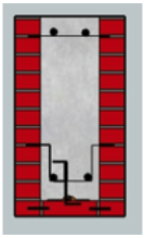
There are some unique features to this detail. One is that the bottom face bricks are pinned to the center bricks; this supplements the mortar bond. Then a horizontal bar is epoxied to the top of the bottom brick so that the “Z”-shaped anchors can hook under the horizontal bar and be embedded in the grout core.
Summary:
– Brick beams are an excellent structural choice.
– Masonry grout acts compositely to create the beam.
– Industry details don’t show mechanical anchors to the bottom bricks; they rely on mortar and grout bond.
– Using cored bricks, mechanical anchors can easily be designed and installed to provide supplemental support to the bottom bricks.
Thank you again for following this column. Remember, by bonding, we get stronger! Keep the questions coming. Send them and your comments to info@masonrymagazine.com, attention Technical Talk. If you’ve missed any of the previous articles, you can find them online for Bonding with Masonry at Masonry Design (https://www.masonrydesignmagazine.com/?cat=bonding-with-masonry).
David is a PE and SE with Biggs Consulting Engineering, Saratoga Springs, NY, USA (www.biggsconsulting.net). He specializes in masonry design, historic preservation, forensic evaluations, and masonry product development.

