


By David Biggs
This month’s questions come from a mason contractor, engineer, and architect. What questions do you have? Send them to info@masonrymagazine.com, attention Technical Talk.
Q. A mason writes “In looking at the rebar drawings and the contract drawings we found locations at bond beams where the vertical bar below the bond beam is terminated in the bond beam and the next bar is placed above the bond beam causing a break in the vertical bar that we would normally see passing through the bond beam. Most of these locations are at areas where bar joists are setting on the CMU walls. It seems like they are intending that the bar joist will provide support and the vertical bars do not have to pass through. Is this allowed? I fear it puts a hinge in the wall.”
A. Thank you for the question. The detail you provided is shown below. As you described, the vertical reinforcement appears to be discontinuous at the floor level. The wall is load-bearing and also acts as a shear wall.
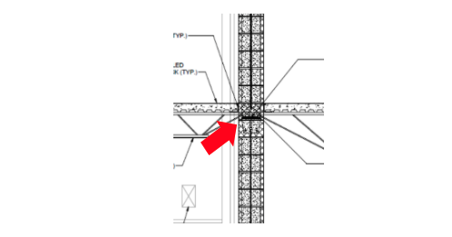
Figure 1 – Vertical reinforcement discontinuous at a floor
There are a few issues to address.
- The vertical reinforcement is not spliced at the joist bearing.
- The bond beam has a solid bottom.
a. Is vertical reinforcement required to be spliced at a floor level or any support level? The answer is yes and no!
If the vertical reinforcement is intended to act as shear wall flexural reinforcement, it needs to be continuous over the wall height. Since this is a shear wall, the bars need to be spliced.
If the vertical reinforcement is not intended to act as shear wall flexural reinforcement but only is used for out-of-plane reinforcement, theoretically it does not need to be continuous over the wall height. The reinforcement can span between the supported levels of out-of-plane support. There is a code exception to the theory; IBC Section 1616, Structural Integrity requires ties for high rise bearing wall structures.
Vertical bars also need proper anchorage at roof levels for an uplift tie-down. The figure below should be evaluated for uplift capacity at the bearing point.
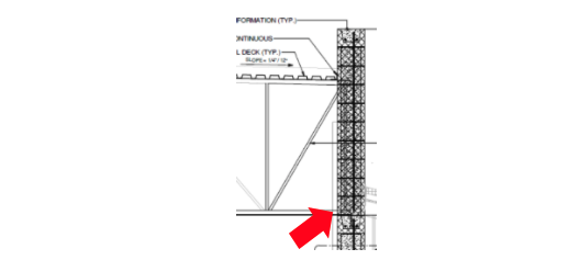
Figure – Roof at bottom chord bearing trusses
b. A second issue that is evident in the details is that solid bottom bond beams are shown in conjunction with the vertical reinforcement. The following detail was shown at intermediate bond beams.

Figure – Intermediate bond beam
The question that occurs is how does a mason extend the bars through the solid bottom? The International Masonry Institute’s Detailing Series (www.imiweb.org) offers two options. The first shows the solid bottom notched to receive the vertical reinforcement (see next figure). The notch needs to be wide even to provide grout cover around the bar (1/4 inch for fine grout; ½-inch for coarse grout). A construction disadvantage of this detail is the inability to grout the unit below. Therefore, grout pours are limited by the bond beam spacing.

Figure – Notched solid bottom
The preferable detail is to use open-bottom bond beams (stretcher units with knockout webs) as shown in the next detail from IMI. Some manufacturers supply the webs pre-cut; otherwise, the mason will have to field cut them. Knockout webs allow continuity of the grout and do not restrict pour heights.

Figure – Knock out webs
Summary: For your project, both items should be the subject of an RFI to clarify the need for bar splices at bearings and open bottom bond beams.
Q. An engineer asks about torsion of masonry beams and lintels. The building uses a steel-framed structure. The exterior walls are masonry cavity walls. The following figures show a long-span masonry opening with the veneer supported off the masonry beam. The ceiling elevations vary.
The beam supports not only the vertical load of the veneer in torsion, but it also must resist out-of-plane lateral loads.

Figure – Veneer supported by masonry beam


Figure – Partial wall elevation (16-foot wide opening)
A. The figure below shows the loads imposed on the CMU beam. The shelf angle cannot independently support the veneer for the large opening without being bolted to the masonry beam. Therefore, the eccentricity of the veneer on the angle produces torsion on the CMU beam.
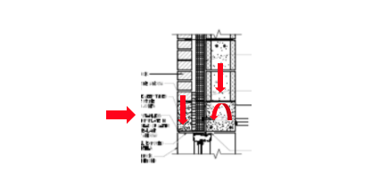
Figure – Torsional, lateral, and axial loads on masonry beam
The masonry standard, TMS 402, does not address the torsion of beams. However, that does not mean torsion does not exist. It’s up to the engineer to decide how to accommodate it. Three possible options include:
- Brace the masonry to the steel frame: If the ceiling is low enough, steel bracing could be hidden above the ceiling as shown conceptually in the next figure. Vertical masonry reinforcement is needed to strengthen the wall itself. (The same bracing could apply for load-bearing walls if there was no frame.)
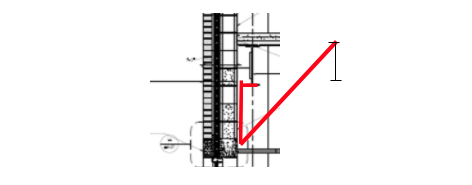
Figure – Bracing
The masonry course supporting the angle must also be properly anchored to the wall. See option 3 below.
2. For the second option, consider applying “concrete theory” for torsion (ACI 318-R14, Section 22.7). For concrete, the beam is analyzed for:
- flexure due to vertical loads
- flexure due to horizontal loads
- shear
- torsion
Horizontal reinforcement accommodates the flexural loads. If the allowable stresses are exceeded for shear and torsion loads, closed ties are added to the horizontal reinforcement.
If we extend this theory to reinforced masonry, the flexural loads are handled similarly by using horizontal reinforcement. Masonry beams are solid grouted and often utilize single-leg vertical stirrups, but placing closed ties in the cells of CMU is more problematic than for concrete and should be avoided whenever possible.
Therefore, consider evaluating the perimeter stresses (see next figure) due to combined shear and torsion and then limiting the overall span or the span between torsional braces to avoid the need for closed stirrups.
Figure – Torsional beam perimeter
To determine the ultimate torsional capacity of the masonry beam, ACI Table 22.7.4.1(a) provides Tth = λ f’c (A2cppcp ) for solid sections. To avoid the need for closed stirrups, the calculated Tu for the beam must be less than φTth. f’m can be used for f’c. The beam can be designed for shear using masonry beam methods to determine if single-leg vertical stirrups are needed.
3. For the third option, the wall can be braced at the floor lines to resist the torsional and lateral loads. The wall cantilevers above and below the floor. The next figure shows torsional restraints added at the floor beam to brace the wall.
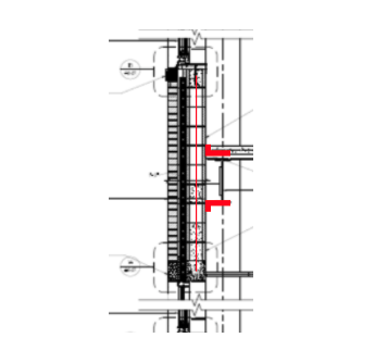
Figure – Torsional restraints
Besides bracing the wall as a panel, the bottom course must also be anchored to resist the torsion at the point of support of the angle that supports the veneer. The next two figures illustrate the action of the torsional loads on the bottom course. Providing anchorage for the bottom course reinforcement will help stabilize the torsion.
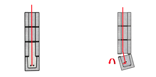
Figure – No Torsion Figure – With Torsion
Summary: The masonry standard does not address torsion of masonry beams. Engineers are left to design to either avoid it altogether or to be creative using bracing or methods derived for concrete beam theory.
Q. An architect has a project to design an addition to a commercial building. The project has a small budget. The existing building is one-story with a cavity wall with brick veneer. She has been able to find matching brick but asks whether it is possible to replicate the color and texture of the existing mortar for the addition without specifying special mortar.
A. This is a common situation. Often budgets don’t allow for the pre-testing and evaluation of materials that is preferred. Regarding mortar matching, experienced masons can use trial and error and get a very close match; others use tinting to match the color. A paper that discusses a field method for mortar replication is available at http://canadamasonrydesigncentre.com/download/9th_symposium/MORTAR02.pdf.
Your initial decision includes selecting the appropriate mortar type for the project. ASTM C270, Type N is the common mortar type for veneers and older projects; Type S is more likely for single wythe construction.
Once you know the type desired, the key to matching mortar color and texture is to select sand that closely matches the color and gradation of the sand used in the original mortar. Since sands are most often locally sourced, finding a similar source may or may not be time-consuming. Again, masons will usually have experience with several sandpits and can obtain samples.
Obtaining a sample of the existing sand can be quite simple using acid digestion. This works well for aggregates that are not acid-soluble, like limestone and marble. Using hydrochloric acid or multiple applications of muriatic acid will dissolve the cement or lime binder. Rinse the final solution and the sand will remain. Use this to compare the sands from your potential new sources.
Once you have the sand, dry mix the sand with the binder (lime and cement) in the proportions required of the mortar type specified. Compare chunks of the existing mortar to the dry mix for color. Experiment with both grey and white cements. Once you have the best dry mix, use that as the source for a wet sample. It may take a few samples before you find the right combination. To match the texture requires a skilled mason who does not over work the tooling.
There will be colors that simply cannot be matched without tinting. For those, match the sand gradation and get the right proportions of binder first and then add the tinting.
Summary: Field replication of mortar using sand, cement and lime is possible except for colors like black and red. Tinting is possible as well.
Keywords for this issue: lap splices, bond beams, knockout webs, torsion, beams, mortar replication, tinting
Thank you again for following this column. Remember, by bonding we get stronger! Keep the questions coming. Send them and your comments to info@masonrymagazine.com, attention Technical Talk. If you’ve missed any of the previous articles, you can find them on-line for Bonding with Masonry at Masonry Design (https://www.masonrydesignmagazine.com/?cat=bonding-with-masonry)
David is a PE and SE with Biggs Consulting Engineering, Saratoga Springs, NY, USA (www.biggsconsulting.net). He specializes in masonry design, historic preservation, forensic evaluations, and masonry product development.
David is a PE and SE with Biggs Consulting Engineering, Saratoga Springs, NY, USA (www.biggsconsulting.net). He specializes in masonry design, historic preservation, forensic evaluations, and masonry product development.