


Bonding with Masonry
This month’s questions come from a manufacturer’s representative and a couple of architects. What questions do you have? Send them to info@masonrymagazine.com, attention Technical talk.

Q. A manufacturer’s representative writes:
I just left a meeting with a mason and an architect where we had a discussion on mortar types.
The masonry walls are to have a cavity wall of 4-inch architectural CMU veneer with a CMU backup. The veneer will extend about 2 feet from grade; above the wall will have EIFS installed over the CMU backup. The window openings will have CMU sills.
There will be a sidewalk alongside the wall and the architect said the owners will be using salt deicers during the winter. The mason wants to use Type N mortar for the veneer and sill and caulk the mortar at the sill. I thought Type S mortar was more appropriate for the veneer and sill. The only point I won was to use a post–applied clear water-repellent. Is there a right answer?
A: Thank you for the question! There is no “right” answer because there is no code item that specifically addresses the use of deicers adjacent to a wall. We can offer and opinion and some information that you the team can use in making a decision.
- Designers usually take mortar type recommendations from ASTM C 270, Standard Specification for Mortar for Unit Masonry. Table X.1.1 Guide for the Selection of Masonry Mortars. ASTM suggests Type S for masonry at or below grade. Type N is a suggested alternative. However, ASTM does not address mortar selection for the condition of using deicers.
- Additional guidance comes from NCMA TEK 5-1B, Concrete Masonry Veneer Details which recommendations Type N mortar more for flexibility. Again, resistance to deicing salts is not mentioned.
- Preferably, no masonry wall should be exposed to deicers. However, the reality is they are used and the masonry will be negatively impacted, both the mortar and the units. Precautions can be proposed to mitigate possible problems.
- If possible, snow and ice removal could be followed by sanding rather than deicing. Deicers should be avoided or used sparingly.
- Deicers come in different formulations, usually containing a chloride. While chloride-based deicers are rated as the most effective, they are also the most damaging to concrete and masonry and adjacent greenery.
- An alternative deicer that is available uses calcium magnesium acetate (CMA). These deicers do not have chlorides and reportedly are less harmful to concrete and masonry and not harmful to plants. Many highway departments have used CMA formulations for years.
- You also mentioned using a post-installed water repellent. In general, this is a good idea for architectural veneer. It creates one more barrier to moisture and deicer intrusion at grade.
- Finally, there is the use of mortar or caulk at the sills. NCMA TEK 5-1B provides guidance here. The following figure shows the recommended detail. The flashing, drip edge and weeps are essential parts of the detail.
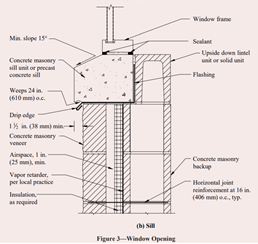
Let make a few comments about the detail.
Sealants are shown inside and outside between the window frame and the sill. This seems reasonable. However, don’t forget the building code. A part of IBC Section 1405.4 states:
“1405.4 Flashing. Flashing shall be installed in such a manner so as to prevent moisture from entering the wall or to redirect that moisture to the exterior. Flashing shall be installed at the perimeters of exterior door and window assemblies, penetrations and terminations of exterior wall assemblies, exterior wall intersections with roofs, chimneys, porches, decks, balconies and similar projections and at built-in gutters and similar locations where moisture could enter the wall.”
This code section implies a flashing flange or additional flashing is needed around windows and doors as a barrier to prevent water infiltration. Sealants may not be sufficient by themselves.
The TEK detail shows a section through the sill. However, it does not show the end of the sill which preferably would have an end dam. The end dam flashing would be recessed from the face of the joint.
The sill should be set in mortar. The bed joints above the sill flashing and at the head joint at the end dam should be raked out and filled with backer tape or backer rod and then sealed. This allows for differential movement. Weeps holes above the flashing should be left open.
In summary:
- Eliminate or minimize the use of deicers near the walls. Notify the Owner of the potential harm and need for on-going maintenance.
- If deicers are used, we suggest using Type S mortar as suggested by ASTM C270 for walls near grade.
- Apply a post-installed water repellent. Maintaining the repellent and sealants should be done periodically; don’t wait until a problem occurs.
- Use sealants around sills and keep weeps open.
Q. An architect writes that his engineering consultant is requiring special seismic anchors for the anchored veneer. The contractor has submitted an RFI indicating these anchors have not been required for projects in the area by other consultants. Why are they needed on this project?
As a follow-up, the architect indicated the project is for a two-story fire station in a city where the site/project is rated as Seismic Design Category is B. The veneer is clay brick laid in stack bond. The building code in effect is the 2015 IBC. The design includes seismic anchors that include wire reinforcement in the bed joints that are mechanically-connected to the anchors.
- Thanks, this is an interesting issue. Let’s work through the code. The 2015 IBC references the masonry standard Building Code Requirements for Masonry Structures (TMS 402-13/ACI 530-13/ASCE 5-13) for design.
TMS 402, Chapter 12 provides criteria for anchored veneer. Section 12.2.2.10.3 Requirements in seismic areas indicates additional conditions for veneers must be implemented for seismic design categories (SDC) C and above. Since your project is in SDC B, nothing special is required per this Section. Standard anchors and spacing are acceptable by this criteria.
However, there is more to consider so let’s clarify.
- Prior to the 2013, TMS 402 required mechanically-attached wire reinforcement, but only for projects with SDC E or F. SDC B was never included in the categories requiring mechanical attachment or joint reinforcement.
- The veneer for your project is specified to be laid in stack bond. In code language, stack bond is one form of masonry bond that fits the description of “not laid in running bond”. TMS 402-13, Section 12.2.2.9, Veneer not laid in running bond requires horizontal wire reinforcement in bed joints not exceeding 18 inches on center. So, we find a clear justification for the wire reinforcement based upon the veneer bond. However, there are no requirements to mechanically attach the wire reinforcement to the anchors.
- Some states or cities adopt their own amendments to the building code or still reference an earlier version of TMS 402. For example, New York City has a 2014 NYC Construction Codes that are based upon the 2008 TMS 402. Therefore for projects with SDC C and higher mechanically-attached wire reinforcement is required. The point here is that designers need to search the local code and amendments.
In summary:
Based upon the code, the veneer design:
- requires wire reinforcement in the bed joints due to the stack bonding, not due to seismic requirements.
- does not require the mechanical attachment of the wire to the anchor. However, the project engineer may have chosen to mechanically attach the veneer for other reasoning.
- does not require a reduced anchor spacing common for high seismic zones.
Q. An architect reports her energy consultant is suggesting specifying non-metallic anchors for brick veneers. The anchors would be used for cavity walls with CMU backup. The purpose of eliminating the metal is to reduce thermal transmission through the wall system. The consultant did not offer a specific anchor but suggested having anchors made from fiber reinforced polymer (frp). What are the drawbacks to such a solution?
A. This is an issue we’ve heard several times in recent months. Thank you for sharing it.
Current masonry practice is to use metal anchors and ties for anchored masonry veneers. However, there are continuous discussions going on in professional circles about minimizing thermal bridging effects on buildings. Therefore, metallic veneer anchors and ties have a recent target of concern. Basalt and carbon fiber have been proposed by researchers for use as masonry anchors and ties. However, we are not aware of any commercial products of any labor organizations training to install such products. We can’t address those issues in this article, so let’s turn to the codes again about using frp.
In accordance with the IBC, masonry veneer anchor design is governed by TMS 402, Building Code Requirements for Masonry Structures. In addition, TMS 602, Specification for Masonry Structures provides governing specifications.
Looking at Chapter 12 – Veneer of TMS 402-16, anchored veneer anchors are to be either a) designed rationally or b) detailed prescriptively. Since most projects are detailed using the prescriptive method, let’s talk about that first.
Prescriptive detailing
In short, the prescriptive method provides alternatives for detailing masonry anchors and their spacing. Prescriptively, limitations are placed on various commercially available anchors based upon the backup structure. However, all the anchors must be metallic. There are no alternatives.
Rational method
For the rational design of anchors, designers have more freedom of choice. The methodology (termed alternative design) allows the designer discretion with selection of both the anchor spacing and type based upon performance. The performance criteria given in Section 12.2.1, Alternative design of anchored masonry veneer is structural only. It does not specifically address fire rating, corrosion, thermal characteristics, or other pertinent criteria. The section also does not specifically mention requiring metallic anchors. Therefore it seems that from a design perspective, non-metallic veneer anchors might be an option.
However turning to TMS 602, Specification for Masonry Structures, Article 1.1 B, we are told that “The Specification supplements the legally adopted building code and governs the construction of masonry designed in accordance with the Code.” Within the Specification, Articles 2.D and 2.E both require metallic anchors and ties. Therefore based upon the Specifications, only metallic anchors are allowed for anchored masonry veneer anchors and ties; frp-based veneer anchors and ties or any other non-metallic anchors and ties would not be code compliant.
In summary:
Current building codes require metallic anchors.
However, manufacturers of anchors and ties are aware of the energy concerns regarding their products and several innovations have come on the market to reduce thermal transmission. These innovations include using thermal spacers or modifying the configuration of anchors and ties to minimize thermal bridging. If thermal bridging is a topic of interest, designers should look into the benefits of such products.
Thank you again for following this column. Remember, by bonding we get stronger! Keep the questions coming. Send them and your comments to info@masonrymagazine.com, attention Technical Talk.
Additional News: The 13th North American Masonry Conference (NAMC) will be held in Salt Lake City, June 16-19, 2019 in conjunction with The Masonry Society. An international audience of academics, practitioners and masons will be discussing the latest research and trends in masonry. Visit https://masonrysociety.org/13namc/ for more information.
David is a PE and SE with Biggs Consulting Engineering, Saratoga Springs, NY, USA (www.biggsconsulting.net). He specializes in masonry design, historic preservation, forensic evaluations, and masonry product development.