By David Biggs
This month’s questions come from a Mason Contractor, an Architect, and an Engineer. What questions do you have? Send them to info@masonrymagazine.com, attention Technical Talk.
Q. A Mason Contractor writes that he is being criticized for constructing exterior single-wythe CMU walls that have hairline vertical shrinkage cracks. The Architect and Owner are both expecting no cracks. The walls are fully-grouted, 12 inches thick with bond beams reinforced with #6 at 16 inches on center. Movement joints are 60 feet apart. The cracks are less than 1/64” and spaced about 8 feet on center.
A. Thank you for the question. The National Concrete Masonry Association (NCMA) provides TEK Notes that are the industry standards for CMU construction. Within the TEK Notes, there are two design methodologies for shrinkage crack control, the Empirical Method and the Alternative Engineered Method. Both are intended to control cracking rather than eliminate cracking provided the CMU is manufactured to ASTM C90 standards.
The Empirical Method (TEK Note 10-02D) uses closely placed movement (control) joints and horizontal reinforcement. Tabulated joint spacing values are based on the use of horizontal reinforcement. This is the most conservative method for planning crack control.
The Alternative Engineered Method (TEK Note 10-03) has two options. The first uses the Crack Control Coefficient (CCC) of the masonry which is based on the shrinkage coefficient determined by ASTM C426, Standard Test Method for Linear Drying Shrinkage of Concrete Masonry Units and Related Units. With sufficient horizontal reinforcement, this option can potentially extend the movement joint spacing determined by the Empirical Method.
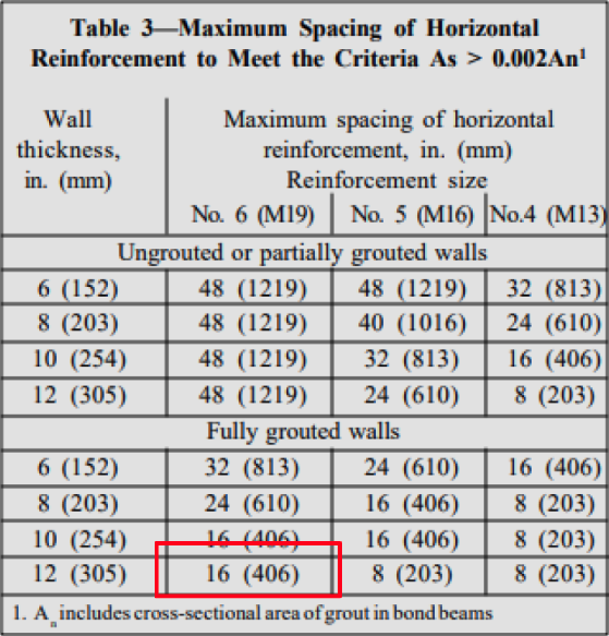
The second option for the Alternative Engineered Method is to eliminate or greatly extend the spacing of movement joints. This method requires significantly more horizontal reinforcement than the Empirical Method, but the effects can be dramatic in reducing movement joints. TEK Note 10-03 has Table 3 to determine the necessary horizontal reinforcement of 0.002An.
From Table 3, 12-inch, fully grouted walls require horizontal reinforcement of at least No.6 bars at 16 inches on center to extend or eliminate movement joints. As you have described your project, this is the option that was likely used by the designers.
Per the TEK Note, the expectation is vertical shrinkage cracks might occur in the wall but would not exceed 0.02 inches (greater than 1/64 inch). There are post-applied sealers for exposed CMU that can bridge shrinkage cracks of 0.02 inches and keep the wall water-resistant.
Summary
1. Shrinkage crack control does not mean there will be no cracks. However, cracks will usually be less than 0.02 inches if the NCMA requirements are met.
2. For this project, the design seems consistent with the NCMA TEK recommendations and the size and spacing of vertical hairline cracks are consistent with the anticipated performance.
Q. An Architect is designing a brick façade using cavity wall construction with cold-formed metal framing. She would like to the brick match the appearance of an existing building that has stepped corbelling or recesses (see Figure 1). Is this possible? From the age of the building and the visible headers, the existing building likely has a solid or mass wall, and not a cavity wall. The corbels project ½ inch.

A. Corbelling is a great way to introduce texture and character to a wall. TMS 402/602, Building Code Requirements and Specification for Masonry Structures governs the design of corbels in Chapter 5 of TMS 402. Designers can use the prescriptive criteria found in Chapter 5 or engineer their solution using Chapters 8 or 9. Most choose the prescriptive method.
When corbelling using the prescriptive method, the code is specific. There are two options depending on the wall type.
The first option is for a solid wall (see Figure 2). This would have been used for the wall in Figure 1. The allowable total corbelling is up to 1/2 the nominal wall thickness. Each corbel step is limited to half the unit height or 1/3 the unit thickness.

The second option applies to cavity walls (see Figure 3). The total corbelling is up to 1/2 the nominal veneer thickness. Each corbel step is limited to half the unit height or 1/3 the veneer thickness. There is a further requirement that corbelled or recessed brick for cavities must align within 1 inch. Compared to solid wall corbelling, the allowable corbelling for a cavity wall is much less.

For your project that uses standard veneer brick (3 courses per 8 inches). The maximum veneer corbel can be the lesser value of 1-inch maximum back offset, ½ (8”/3) = 1.33 inches, or 1/3 (4”) = 1.33 inches. The 1” offset governs, and the proposed ½ inch recess is acceptable for cavity walls.
Summary
1. TMS 402 provides prescriptive criteria for both solid (mass) walls and cavity walls.
2. Compared to solid wall corbelling, the allowable corbelling for a cavity wall using the prescriptive method is much less. If larger corbels are desired, they must be engineered using Chapter 8 or 9.
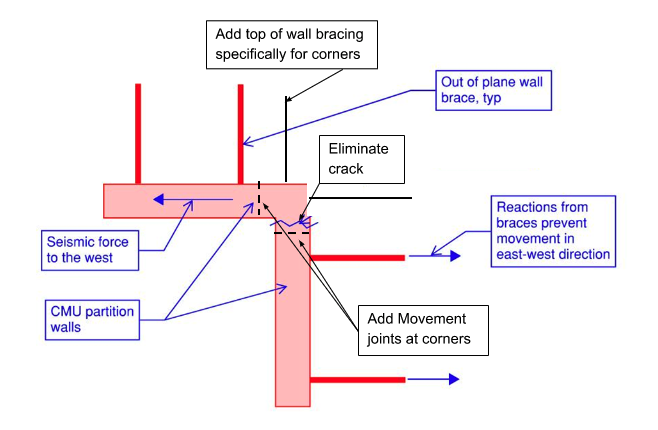
Q. An Engineer writes that they commonly specify partial height CMU as partition walls (not shear walls) for buildings within seismic zones. This requires kicker braces at the top of the wall, to prevent it from failing out-of-plane. However, these kickers are supposed to also slide a bit, to allow the wall to move in-plane without attracting too much shear. The problem happens at corners. For example, an east-west wall wants to slide in the west direction, but it’s tied into a north-south wall that’s braced out-of-plane. The north-south wall can’t move to the west, so a crack develops at the corner (see Figure 4). Do you have any advice?

A. Corner crack control is important. Your partitions are non-participating; they are not intended to act as lateral load-resisting (shear) walls, except for self-weight, and must be isolated from the building structure above as you’ve done.
To prevent the corner cracking that you’ve mentioned requires either heavily reinforcing the corner as would be done for a participating wall or isolating the corner with movement joints. For the seismic movement on this project, movement joints are recommended at the corners, so shear does not transfer around the corner.
In general, masonry corners prefer to have movement joints. These joints should function in tension or compression and not in shear since the sealants will fail prematurely in shear. The wall segments away from the corner get designed for self-weight in-plane effects, the corner gets braced for out-of-plane loads in both directions (see Figure 5 with proposed modifications).
Summary
1. Partitions walls need to be isolated from the structure, so they do not attract in-plane lateral loads.
2. Corners should be isolated also to avoid shear transfer around the corner.
Thank you again for following this column. Remember, by bonding, we get stronger! Keep the questions coming. Send them and your comments to info@masonrymagazine.com, with attention to Technical Talk. If you’ve missed any of the previous articles, you can find them online for Bonding with Masonry at Masonry Design (https://www.masonrydesignmagazine.com/?cat=bonding-with-masonry).
Keywords for this issue: crack control, veneer corbelling, recess veneer, corner movement joints, partitions
About the Author
David is a PE and SE with Biggs Consulting Engineering, Saratoga Springs, NY, USA (www.biggsconsulting.net), and an Honorary Associate Professor with the University of Auckland, NZ. He specializes in masonry design, historic preservation, forensic evaluations, and masonry product development.

